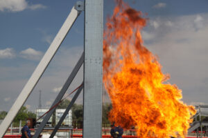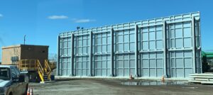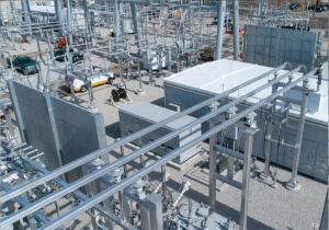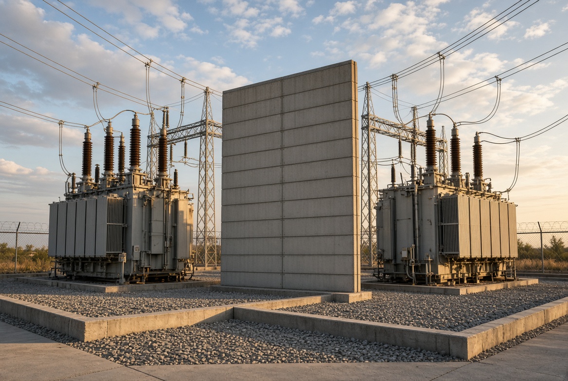
A fire barrier may be required when oil-filled power transformers present a fire hazard and sit too close to each other or a building. It may also be needed near combustible materials, exits, doors, or windows. Space, suppression, and oil containment may serve as other safeguards.
The final decision depends on the adopted code, fluid type, oil volume, site layout, nearby assets, utility rules, insurer criteria, and local approval. Transformer fire walls can limit heat, flame, oil-fire spread, and damage to nearby equipment. A site review should also account for drainage, emergency access, maintenance space, and future equipment removal.
When Is a Fire Barrier Required Between Power Transformers?
What Conditions Create a Fire Exposure Between Transformer Units?
A fire exposure exists when a fault in one transformer can spread heat, flames, burning liquid, or hot debris toward another unit. The risk is highest with transformers that contain combustible mineral oil. A tank rupture can release oil across the pad or into nearby drains. Fire can then reach radiators, bushings, cables, control boxes, or the next transformer. Small spacing also increases the risk that radiant heat will damage nearby equipment before crews can control the situation.
The site layout shapes the need for a barrier. Designers review the oil volume, fluid type, clear distance, and direct line of sight between units. They also check containment pits, drainage paths, suppression systems, and access for fire crews. Conservator tanks and radiators may extend beyond the main tank, so measurements cannot rely solely on the tank body.
Openings in nearby buildings can create another path for heat and smoke. A fire wall may be needed where spacing cannot limit that exposure. A standard fire wall does not always resist blast pressure, so that hazard needs a separate structural review.
Which Codes, Standards, and Site Rules Control the Decision?
The adopted electrical code controls the minimum legal duties for the project location. NEC Article 450.27 addresses outdoor oil insulated transformers near combustible materials, buildings, fire escapes, doors, and windows. It permits several forms of protection, including space separation, fire resistant barriers, automatic fire suppression, and oil containment. The local authority applies the adopted edition and decides if the proposed method meets its rules. State rules, building codes, fire codes, and permit terms may add other duties.
Other documents can shape the final design. NFPA 850 gives fire protection recommendations for electric generating plants and high voltage converter stations. IEEE 979 gives design guidance for substation fire protection. FM Data Sheet 5 4 sets property loss prevention recommendations that an insurer or owner may request.
Utility standards and company rules may set stricter spacing or wall details. These documents do not all carry the same legal weight. The project team should record which rules apply, which party has approval power, and which design basis supports the chosen barrier.
How Much Separation Can Replace a Transformer Fire Wall?
How Do Oil Volume, Fluid Type, and Building Construction Affect Distance?
Oil volume is one of the main factors that affects separation. A larger oil supply can feed a larger fire and produce a wider heat zone. NFPA 850 criteria list line of sight distances of 5 feet for less than 500 gallons, 25 feet for 500 to 5,000 gallons, and 50 feet for more than 5,000 gallons. A documented site analysis may support a different result.
Fluid type also matters. Mineral oil can create a greater fire load than a fluid listed as less flammable. Still, a lower risk liquid does not remove every spacing need. The design team reviews tank size, spill area, nearby equipment, and fire protection systems.
Building construction changes the exposed target. A combustible wall may need more distance than a noncombustible or fire rated wall. Doors, windows, roof edges, and air openings can increase exposure. FM Data Sheet 5 4 uses different distances for rated, noncombustible, and combustible walls. Its figures measure from the inside edge of containment. The final distance must follow the adopted rules and site approval.
Why Is There No Single Clearance Number for Every Site?
There is no single clearance number because transformer fire protection depends on more than tank spacing. Different documents serve different purposes. The adopted electrical code may set legal minimums. NFPA 850 addresses generating plants and high voltage converter stations. IEEE 979 covers substation fire protection. FM Data Sheet 5 4 supports property loss prevention. A utility, insurer, owner, or local authority may set another limit.
Each method may also measure distance from a different point. One rule may use the transformer casing. Another may use the edge of a predicted oil spill or containment area. Radiators, conservator tanks, bushings, and nearby roof areas can change the fire path.
Site conditions add more variables. Designers review oil amount, fluid class, wall construction, fire suppression, drainage, relay speed, replacement time, and the value of nearby equipment. Wind, grade, access, and future maintenance can affect the layout too. A number copied from another project may be too small or needlessly large. The design basis should name the governing documents, measurement points, accepted risk level, and approving authority.
What Fire Rating, Height, and Width Should the Barrier Have?
How Do Two Hour and Three Hour Ratings Apply?
A two hour fire resistance rating often applies to outdoor transformer separation. NFPA 850 criteria use a two hour wall for outdoor oil insulated transformers where spacing does not provide enough protection. FM Data Sheet 5 4 also calls for a two hour barrier between adjacent outdoor transformers when its listed separation distances cannot be met.
The rating describes how long a tested wall assembly resists a standard fire test. It does not mean the wall can stop every tank rupture, pressure wave, or flying part. Those hazards need a separate structural review.
A three hour rating usually appears in a different setting. NFPA 850 applies it to specified indoor oil insulated equipment and some indoor units that use less flammable or nonflammable fluid. FM also uses a three hour barrier in certain designs that protect a main building. It pairs that wall with stated spacing and roof protection details.
The project team should select the rating from the governing code, owner criteria, insurer rules, and approved design basis. Openings, joints, supports, and service penetrations must follow the tested wall assembly.
How Far Should the Wall Extend Above and Beyond the Transformer?
The barrier must block the main paths for flame, radiant heat, burning oil, and hot debris. For a wall between adjacent outdoor transformers, NFPA 850 criteria call for a height of at least 1 foot above the transformer casing and oil conservator tank. The wall should also extend at least 2 feet past the transformer and cooling radiators. If the containment edge reaches farther, the wall should reach that point. These dimensions may change when a documented fire protection analysis supports another layout.
FM Data Sheet 5 4 uses a similar approach. It calls for the barrier to reach 1 foot above and 2 feet past transformer parts that may become pressurized during an electrical fault. These parts include bushings, pressure relief vents, radiators, and tap changer enclosures.
Designers should measure every exposed component, not only the main tank. They should also check grade, oil flow, nearby roofs, doors, cable routes, and maintenance access. A taller or wider wall may be needed when the basic dimensions leave a direct fire path.
What Can Be Used Instead of a Fire Barrier?
Can Space, Suppression, or Oil Containment Meet the Site Need?
Space can replace a transformer fire wall when the adopted rules accept spatial separation and the available distance limits fire spread. Designers must use the correct measurement point. Some rules measure from the transformer tank. Others measure from the nearest edge of oil containment. Nearby radiators, bushings, cable trays, roof lines, doors, and windows can affect the safe distance. The chosen layout must also leave room for inspection, repairs, and fire crew access.
Automatic suppression may provide another approved form of protection. Water spray can cool the exposed transformer and control flames. The system needs a reliable water supply, proper coverage, detection, drainage, and testing. Oil containment controls where released liquid flows. Curbs, pits, drains, and stone beds can keep burning oil from reaching nearby equipment.
Still, containment does not block radiant heat by itself. Many sites use a combined plan with space, suppression, containment, and fast electrical isolation. The approving authority, owner, utility, and insurer must accept the final method.
When Can Ester Fluid or a Retrofit Lower the Fire Exposure?
Ester fluid can lower fire exposure because natural and synthetic ester liquids often have much higher fire points than mineral oil. Some products carry approval as less flammable transformer fluids. FM Data Sheet 5 4 allows shorter separation distances in certain layouts that use approved fluids and approved transformers. The exact distance still depends on liquid volume, equipment approval, containment, and nearby exposures. Changing the fluid does not remove all fire barrier duties.
A fluid retrofit must suit the transformer. The manufacturer should review seals, gaskets, cooling limits, loading, moisture levels, and material compatibility. The work may include draining, flushing, filling, sampling, and electrical tests. A larger transformer may need a detailed cooling review because ester fluid can behave differently from mineral oil.
Other retrofit options include faster fault clearing, pressure relief equipment, improved drainage, added water spray, moved equipment, or a rated barrier. The project team should compare outage limits, cost, service access, and approval needs before selecting the work.
What Mistakes Cause Transformer Fire Wall Projects to Fail?
What Design Errors Affect Openings, Drainage, Access, and Foundations?
Poor planning can weaken a transformer fire wall before installation starts. Openings for cables, pipes, ducts, and bus systems can let heat, flame, and smoke pass through the barrier. Each opening needs a tested protection method that matches the required wall rating. Doors, dampers, seals, joints, and supports also need the correct rating. An unsealed gap can reduce the value of the full assembly.
Drainage errors can spread burning oil toward another transformer or building. The containment area should direct released fluid away from exposed equipment. It must also handle water from an installed spray system. Blocked drains, poor grading, and undersized basins can cause overflow.
Access problems can block maintenance, fire crew movement, or transformer removal. The layout should allow space for tools, lifting equipment, radiators, and replacement work. Foundation plans must account for soil conditions, wall weight, wind loads, seismic forces, and settlement. Structural drawings and drainage calculations should form part of the project review.
Who Must Approve the Plan Before Installation?
The authority having jurisdiction gives the required code approval. This party may be a local building department, fire official, electrical inspector, or another public office. The exact role depends on the laws and code editions adopted in that location. NFPA defines this authority as the organization, office, or person responsible for enforcing a code or standard. The project team should confirm the approving office before final design begins.
Other parties may require separate acceptance. The owner may set property protection goals. The serving utility may have equipment and clearance rules. An insurer may request a plan review based on its loss prevention standards. The transformer maker may also need to approve clearances, access, cooling, or changes near its equipment.
A complete submission should include site plans, wall dimensions, structural details, fluid data, drainage calculations, fire protection drawings, and equipment clearances. Written approvals should be collected before materials are ordered. Early review can reduce redesign, permit delays, and costly site changes.
Frequently Asked Questions
Is a Fire Wall Needed Between Two Dry Type Transformers?
Not always. Dry type transformers do not contain combustible insulating oil, so they pose a lower liquid fire risk. Spacing, room construction, ventilation, voltage, and local code rules may still require separation. The approving authority should confirm the final layout.
Can a Building Wall Serve as the Transformer Fire Barrier?
Yes, a building wall may serve as the barrier if it has the required fire rating and construction. Doors, windows, vents, roof edges, and wall openings can weaken its protection. The wall must also extend far enough to block heat and flame paths.
What Is the Difference Between a Fire Wall and a Blast Wall?
A fire wall limits flame, heat, and smoke spread for a rated period. A blast wall resists pressure and flying debris from an equipment failure. One wall may provide both functions only when its tested design and structural rating cover both hazards.
How Much Does a Transformer Fire Wall Cost?
Cost depends on wall size, fire rating, material, foundation work, structural loads, site access, labor, and shipping. Drainage changes, cable openings, permits, and outage limits can raise the price. A site review and design scope are needed for an accurate quote.
Plan Your Transformer Fire Barrier With Sinisi Solutions
Fire barrier planning should start with transformer data, the site layout, nearby exposures, governing rules, and owner loss goals. A sound project scope also covers wall rating, panel reach, wind and seismic loads, oil containment, drainage, equipment access, and future removal needs. These details can reduce redesign, permit delays, shutdown time, and costly field changes.
Sinisi Solutions supports utilities, plants, data centers, and industrial sites with barrier systems shaped around real space limits and operating needs. Our team can review new construction or retrofit conditions and help move the project from site review through installation. Let us review your project; visit us at 75 Main St., Suite 16, Manasquan, New Jersey, 08736, US, or call 732-232-2100 for transformer fire barrier planning and installation support.