A transformer fire barrier is usually the better fit when the main goal is to limit flame spread and radiant heat between oil-filled transformers or nearby assets. A blast wall is more appropriate when the project also has a defined pressure, debris, or impact hazard. The right choice depends on transformer fluid, oil volume, spacing, nearby equipment, containment, structural loads, and site rules.
Many facilities also need to protect maintenance routes and future transformer removal paths. Reviewing tested fire barrier walls can help frame the options before the design scope is set. The wall should match the hazard, not just the label.
What Is the Real Difference Between a Transformer Fire Barrier and a Blast Wall?
Fire, Radiant Heat, and Flame Spread
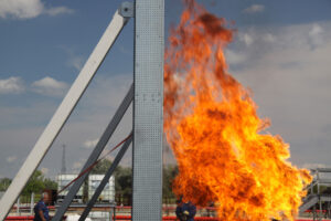
A transformer fire barrier is built mainly to limit fire spread from one transformer to nearby equipment, buildings, or another transformer. Oil filled transformers can release burning insulating fluid after a severe fault or tank failure. Flames and radiant heat can then expose nearby assets. A fire barrier creates physical separation and reduces direct heat exposure. Its fire resistance rating shows how long the wall assembly can resist a standard fire test under stated conditions. That rating does not describe blast pressure capacity by itself.
Wall size and placement also matter. The barrier must block the main path between the transformer and the item being protected. Designers may review the transformer tank, bushings, conservator, radiators, oil containment area, and nearby structures. Material type, wall height, wall width, openings, and joints can affect fire performance. A wall chosen for fire protection should match the site hazard and the applicable code or project standard.
Overpressure, Projectiles, and Structural Loads
A blast wall serves a different purpose. It is designed to resist a defined pressure load and, in some cases, impact from flying debris. A transformer failure can rupture the tank or other components. That event may create a sudden pressure wave and throw metal, insulation, or burning material toward nearby equipment. A wall meant only for fire resistance may not have the strength or support needed for those forces.
Blast design starts with a stated load. Engineers need values such as pressure, duration, impact demand, wall span, support conditions, and distance from the transformer. They also need to account for normal structural forces such as wind and seismic loads where they apply. Foundations and connections must transfer these forces safely into the supporting structure. Some wall systems can provide both fire resistance and blast resistance, but each function needs its own verified design basis. The name of the wall alone does not prove its performance.
Which Site Risks Should Drive the Choice?
Transformer Fluid, Oil Volume, and Fault Scenarios
Transformer fluid is one of the first site risks to review. Mineral oil can burn and add fuel to a transformer fire. Some transformers use fluids with a higher fire point. Those fluids may reduce fire risk, but they do not remove every hazard. The amount of liquid also matters. A larger volume can create a larger spill and a longer burning event if the tank fails. NFPA material lists fluid type, fluid quantity, spill size, nearby construction, transformer power, and fire protection systems as factors in separation planning.
The fault scenario matters just as much as the fluid. An internal electrical fault can create heat, gas, pressure, and tank damage. Bushings and other parts may also fail. Site teams should review realistic events that could affect nearby assets. Fire barrier walls may fit a project focused on flame spread and radiant heat. A blast rated system may be needed where the design basis includes pressure or flying debris. The selected wall should match the stated hazard and the load it may face.
Adjacent Transformers, Buildings, People, and Replacement Risk
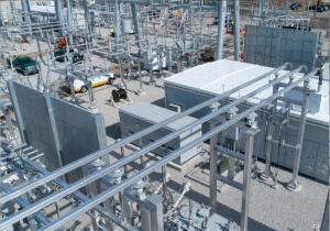
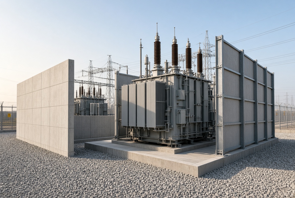
The location of nearby assets can change the barrier choice. A transformer beside another unit can create a fire spread risk if flames or radiant heat reach the second unit. A transformer near a building can also expose walls, roofs, cable areas, and indoor spaces. Public NFPA material uses spacing or fire barriers as ways to reduce exposure between oil filled transformers and nearby structures. It also addresses separation between adjacent transformer units.
People also affect the design decision. A wall may need to shield work areas, access paths, roads, or occupied buildings from a defined hazard. Site layout should still allow safe inspection and maintenance access. Replacement planning matters too. Large transformers may require cranes, trailers, lifting paths, or removable wall sections.
A barrier placed too close to the equipment can create problems during future repairs or replacement. Designers should review both present protection needs and future access before fixing the wall position. Good planning can protect nearby equipment without blocking the work needed through the life of the transformer.
What Do Codes and Separation Rules Mean for the Wall?
NFPA 850, IEEE 979-2025, Insurer Criteria, and Local Requirements
The right standard depends on the type of facility and the project scope. NFPA 850 covers fire protection for electric generating plants and high voltage direct current converter stations. The 2026 edition is the current NFPA 850 edition. IEEE 979 2025 focuses on fire protection for electric substations. IEEE lists it as an active standard, published on April 10, 2026. It replaced IEEE 979 2012.
These documents can shape decisions about transformer spacing, fire barriers, oil containment, and nearby property. They do not remove the need to check project specific requirements. A property insurer may also set loss prevention criteria. For example, FM guidance addresses separation, containment, barrier ratings, and transformer fluid. Local fire codes, building rules, permits, utility standards, and the authority having jurisdiction may add other requirements. The design team should identify the rules that apply before selecting wall dimensions or ratings.
Wall Height, Width, Line of Sight, and Fire Resistance
Wall dimensions affect how well a barrier limits fire exposure. Height alone does not define protection. Width, transformer position, oil containment, radiators, and nearby structures also affect the layout. NFPA 850 committee material states that a firewall between adjacent oil insulated transformers should extend at least 1 foot above the transformer casing and oil conservator tank. It also describes extending the wall beyond the transformer and cooling radiators, or to the edge of the containment area, based on the stated conditions.
Line of sight is another key part of separation planning. The wall should block a direct exposure path between the transformer fire area and the asset being protected. A fire resistance rating measures how long an assembly can resist a standard fire test under stated test conditions. NFPA 850 material uses a 2 hour rated firewall in certain outdoor oil insulated transformer separation cases. The final rating and wall geometry should come from the applicable edition, site layout, oil quantity, and approved project design.
What Installation and Retrofit Limits Affect the Decision?
Foundations, Wind, Seismic Loads, and Available Space
A transformer barrier needs a stable base that can carry the wall and the forces acting on it. Existing foundations may not have enough capacity for a new wall system. This matters most during retrofit work. The design team should review concrete strength, footing size, soil conditions, anchor locations, and nearby buried services. Wind can place strong lateral pressure on a tall wall. Seismic forces can also affect the wall, connections, and foundation in regions with earthquake design requirements. A blast rated wall may place even greater demand on its supports because pressure loads can act quickly and with high force.
Available space can limit the wall type and position. Existing transformers, fences, roads, cable trenches, and buildings may leave little room. The chosen layout must still provide the required protection while leaving enough space for safe operation and service work.
Drainage, Cable Routes, Maintenance Access, and Equipment Removal
Barrier placement can affect many parts of an existing transformer site. Drainage is one of the main concerns. A new wall should not block the intended flow of water or spilled transformer fluid. Oil containment systems may rely on drains, sumps, pits, curbs, or other features that need clear flow paths. Wall foundations should also avoid damaging buried drainage lines.
Cable routes need similar attention. Power cables, control wiring, grounding conductors, and cable trenches may pass through the planned wall area. Moving them can add cost and increase outage needs. Wall openings must also maintain the required fire performance where applicable.
Maintenance access should remain practical after installation. Workers may need room to inspect bushings, radiators, valves, gauges, and other parts. Future removal matters too. A replacement transformer may need crane access, trailer clearance, or removable wall sections. Planning for those needs early can prevent costly changes later.
Is a Blast Wall Worth the Added Cost?
Engineering, Materials, Site Work, and Outage Cost Drivers
A blast wall usually costs more than a wall built only for fire exposure. The higher cost often starts with design work. Engineers may need defined pressure loads, impact loads, wall dimensions, connection details, and foundation loads. Material choices can also raise the price. Thicker panels, heavier steel, stronger anchors, and larger foundations may be needed for blast resistance.
Site conditions can add more cost. Crews may need to work around existing transformers, cable trenches, oil containment systems, roads, or buried utilities. Limited access can slow installation and require smaller equipment. Outages can also affect the budget. Some work may require deenergized equipment or restricted work zones. A longer outage can affect plant operations. The best cost comparison looks at the full project scope, not just the wall material.
When a Fire Only Barrier May Fit the Project
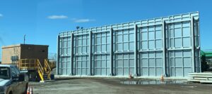
A fire only barrier may fit a site where the main hazard is flame spread and radiant heat. This can apply where the design basis does not include blast pressure or projectile impact. Fire barrier walls can separate transformers from nearby equipment or structures and reduce direct heat exposure. The selected system still needs the proper fire resistance rating, wall size, support, and location.
The choice should match the actual hazard study and site rules. A fire only wall may be a practical option where spacing is limited but blast resistance is not part of the required design. It can also reduce structural demands compared with a heavier blast rated system. Cost savings should not drive the decision by themselves. The wall must still meet the project requirements for fire exposure, oil containment, access, foundations, and nearby assets. A clear design basis helps avoid paying for performance the site does not require.
Frequently Asked Questions
Can a Fire Rated Transformer Wall Also Resist a Blast?
Yes, but only if the wall is designed and rated for both hazards. A fire rating alone does not prove resistance to blast pressure or flying debris.
How Much Space Is Needed Around an Oil Filled Transformer?
Spacing depends on transformer size, fluid type, oil volume, nearby structures, fire protection measures, and the rules that apply to the site. Project teams should use the required code, standard, insurer criteria, and approved design documents to set the final distance.
Does a Fire Barrier Replace Oil Containment or Suppression?
No. A fire barrier limits fire and heat exposure, while oil containment manages leaking transformer fluid. Fire suppression serves a separate purpose, so one system does not automatically replace the others.
Can a Transformer Barrier Be Added to an Operating Substation?
Yes, many barriers can be added as retrofit projects. The work must account for electrical clearances, foundations, cable routes, drainage, access, equipment movement, and any outage needs before installation begins.
Protect Your Transformer Site With Sinisi Solutions
A transformer barrier project should start with the hazard the wall must resist, the spacing available, and the assets that need protection. Fire rating, pressure loading, oil containment, drainage, wind, seismic forces, maintenance access, and outage limits can all change the right wall system. For retrofit work, the design must also fit existing foundations, cable paths, radiators, gates, and transformer replacement routes.
Sinisi Solutions provides site assessment, engineering, fabrication, and installation services for transformer barrier projects. Project teams can review system options at https://firebarrierexperts.com/. For project planning, visit us at 75 Main St., Suite 16, Manasquan, New Jersey, 08736, or call 732-232-2100 for transformer fire barrier and blast wall support. We can help scope a barrier that fits the site, hazard basis, and operating needs.