Updated November 6, 2026
Direct Answer
A transformer fire barrier is a passive 2-hour rated wall that blocks flame and radiant heat between oil-filled transformers and nearby assets. A deluge system is active water spray that depends on detection, a valve, a water supply and containment. FM Global accepts separation, a fire barrier, or water spray as alternatives for exposure protection [1].
TL;DR
- A barrier is in place before, during and after a fault; a deluge system has to detect, trip and flow.
- FM Global DS 5-4 lists separation, a 2-hour barrier, or water spray, any one of three; water spray applies where spacing is not met and barriers are not provided.
- Water spray triggers containment sized for 60 minutes of hose flow at 500 gpm plus three spray systems running at once.
- Deluge upkeep is an annual full flow trip test under NFPA 25 and a long functional checklist; barrier upkeep is a walk-around.
- Outdoor water spray is classed as exposure protection, not guaranteed extinguishment; water mist is the suppression option.
- Deluge runoff can overtop containment and carry oil to a waterway, a Clean Water Act violation; foam leaves residue.
- Generating plant main transformers still get a water spray recommendation under NFPA 850; the barrier limits what that spray has to cover.
One liner: For most oil-filled transformer sites, a passive fire barrier meets the same exposure rule as a deluge system with no water, no trip test and no enlarged basin.
Key Numbers
| Stat | What it measures | Source |
|---|---|---|
| 3 alternatives | Separation, a 2-hour fire barrier, or water spray, any one accepted by FM Global for exposure protection | FM Global DS 5-4, 2020 |
| 2-hour rating | Fire barrier rating FM Global calls for between adjacent outdoor transformers | FM Global DS 5-4, 2020 |
| 1 ft and 2 ft | How far a barrier extends above and beyond pressurizable transformer parts | FM Global DS 5-4, 2020 |
| 0.3 gpm per sq ft | Water spray density over transformer surfaces | FM Global DS 5-4, 2020 |
| 500 gpm for 60 minutes | Fire hose discharge the containment must hold, on top of spray flow, where water spray is used | FM Global DS 5-4, 2020 |
| 250 gpm 1 hr or 500 gpm 2 hr | Hose stream allowance by oil volume | FM Global DS 5-4, 2020 |
| 5, 25 and 50 ft | Separation between containment edges for mineral oil under 500, up to 5,000 and over 5,000 gallons | FM Global DS 5-4, 2020 |
| $15,000 per year | Deluge system maintenance in the Bureau of Reclamation worked example, 2004 dollars | Bureau of Reclamation FIST 3-32, 2016 |
| About 10 to 1 | How much more likely a transformer is to fail without a fire than with one, per FM Global loss data | FM Global DS 5-4, 2020 |
What a Transformer Fire Barrier Does and What a Deluge System Does
In short: A barrier blocks heat with no moving parts; deluge floods the unit through a chain of detection, valve, water and drainage; water mist does the same with less water and higher pressure.
A transformer fire barrier is a wall. A deluge system is a chain, and every link has to hold.
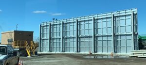
The barrier is a fire-rated panel assembly placed between transformers, or between a transformer and a building, switchgear or cable run. FM Global asks for a 2-hour rating and for the wall to extend 1 foot above and 2 feet past any part that could pressurize in a fault, including bushings, relief vents, radiators and tap changer housings [1]. The modular transformer fire barriers from Sinisi Solutions are built to that geometry and bolted in place with no water, power or sensors attached.
A transformer deluge system is a set of open nozzles on dry pipe. When a heat or flame detector trips the deluge valve, water flows out of every nozzle at once and tries to drown the fire from several angles [2]. A fixed water spray system works the same way with nozzles aimed at the transformer’s shape. FM Global sets the outdoor density at 0.3 gallons per minute per square foot of transformer surface and describes the result as exposure protection, meaning it cools the exposed unit rather than guaranteeing extinguishment [1].
Water mist uses far less water at much higher pressure. Fine droplets absorb heat and displace oxygen, so the system can suppress rather than only cool, but it needs high-pressure pumps and piping that a plant’s existing fire main usually cannot supply [2].
Water mist vs fire barrier and deluge at a glance
| Factor | Fire barrier | Deluge or fixed water spray | Water mist |
|---|---|---|---|
| How it works | Blocks flame and radiant heat between assets | Open nozzles flood the transformer when a detector opens the valve | High-pressure fine spray cools and smothers the fire |
| What it needs to operate | Nothing after installation | Detection, valve, pumps or mains pressure, drainage, containment | Detection, high-pressure pumps, dedicated piping, containment |
| Effect on the fire | Contains it to one unit | Cools exposed surfaces, may control the pool fire | Suppresses in the right conditions |
| Water used | None | High volume, 0.3 gpm per sq ft plus hose streams | Low volume |
| Moving parts | None | Many | Many |
The Water and Containment Load That Deluge Cost Comparisons Leave Out
In short: FM Global requires deluge containment for an hour of hose flow at 500 gpm plus simultaneous spray on three units, a cost hardware quotes leave out.
Most pages that call a deluge system the cost-effective choice price the nozzles, pipe and valve and stop there. FM Global Data Sheet 5-4 does not stop there. Where water spray protects a transformer, it requires containment sized for at least a 60-minute fire hose discharge at 500 gallons per minute, plus the full flow of the spray system, and it tells the designer to assume the spray systems on the transformers either side will run at the same time as the one that activated [1].
Run the numbers. Sixty minutes at 500 gpm is 30,000 gallons of hose water before any spray water is counted. Add three spray systems at 0.3 gpm per square foot of transformer surface, and the basin, drains and oil-water separation have to hold all of it [1]. The water supply has to deliver the same simultaneous demand, and the data sheet adds a separate hose stream allowance: 250 gpm for one hour on units up to 1,000 gallons of mineral oil, or 500 gpm for two hours above that [1]. The containment also needs a system to pump out rainwater so the capacity is there when the fire comes [1].
| Load FM Global attaches to water spray | Requirement | Applies to a fire barrier? |
|---|---|---|
| Containment capacity | 60 minutes of hose discharge at 500 gpm plus spray flow, adjacent systems running together | No |
| Water supply | Simultaneous flow for the fire-origin unit and the unit each side at 0.3 gpm per sq ft | No |
| Hose stream allowance | 250 gpm for 1 hour up to 1,000 gallons of mineral oil; 500 gpm for 2 hours above that | No |
| Rainwater removal | A system to keep the containment empty between events | No |
| Oil spill containment | Required for the transformer fluid itself | Yes |
A fire barrier carries none of that load. Spill containment for the transformer oil itself is still required under FM Global’s rule regardless of what protects the unit [1], but the wall adds no water demand, no drainage upgrade and no larger basin. That difference, not the hardware quote, is where the two options separate on cost.
Cost: Install Day and the Next 30 Years
In short: A barrier is paid once; a deluge system keeps billing for tests, valve rebuilds and containment work for decades.
On install day a deluge system can look competitive. Pipe, nozzles and a valve are a known quote, and many plants already have a fire main. The Bureau of Reclamation, which runs hundreds of oil-filled transformers at hydro plants, describes suppression systems and their containment structures as “complex and expensive” and notes that most mineral-oil sites will still need barrier walls or more separation on top of the spray system to meet NFPA criteria [2].
By year ten the picture changes. In the Bureau’s published life-cycle example for a 10,000-gallon unit, the deluge system needed a $50,000 rehabilitation at year ten and $15,000 a year in maintenance, and the containment that goes with it needed a $100,000 rehabilitation plus $5,000 a year. Over the 50-year study period, suppression maintenance alone came to more than $320,000 in present value. Those are 2004 figures in a hypothetical case, so treat them as proportions rather than quotes, but the shape holds: the water system keeps billing after the spray system is paid for [2].
A barrier’s cost is set by panel count, height, span and foundation, and it is paid once. There is no pump to rebuild, no valve to recertify and no basin to enlarge.
| Cost line | Fire barrier | Deluge or water spray |
|---|---|---|
| One-time install | Panels, footings, crane and crew | Nozzles, pipe, deluge valve, detection, water supply, drainage, containment basin |
| Recurring annual | Visual inspection | Functional test, valve service, detector test, basin pump-out, documentation |
| Ten-year items | None typical | Valve and control rehabilitation, containment rehabilitation |
| What scales the cost | Wall length and height | Transformer surface area, number of adjacent units, water supply distance |
Upkeep: What a Transformer Deluge System Has to Pass Every Year
In short: Deluge systems need an annual trip test and a nine-item functional check; barriers need an inspection walk.
A spray system is only as good as its last test. NFPA 25 sets the inspection, testing and maintenance schedule for water spray and deluge valves, including an annual full flow trip test [3]. The Bureau of Reclamation’s own program lists what that annual functional test has to prove on a transformer deluge system [2]:
- Detectors deenergize the transformer and trigger the water release
- Control circuits, motors, pumps, solenoids and valves all operate
- Water reaches every discharge nozzle and the nozzles are clear of debris
- Containment drain valves close and sump pumps shut off
- Every alarm and indication works
Each of those is a point of failure that has to be found before a fire does. The same document records what happens when the schedule slips: deluge systems abandoned in place, piping and wiring mounted so close to the unit that they could melt before the system operated, and staff who no longer knew what the system was meant to do [2]. Water on an energized transformer also damages bushings and can cause flashover, so testing has to be planned around outages or diverted away from the unit [2].
A fire barrier’s upkeep is a walk-around. Check the panels for impact damage, check the anchors and check that nothing has been stacked against the wall. There is no trip test because there is nothing to trip.
Reliability: Passive vs Active Transformer Fire Protection
In short: A barrier needs no signal to work; a spray system needs every link in its chain to hold within about 30 seconds.
Picture the first thirty seconds of a tank rupture. FM Global’s loss data describes what follows: an oil mist explosion, then a long-burning, high-heat pool fire [1]. In those thirty seconds a deluge system has to sense the heat, confirm it, open the valve, bring water to pressure and deliver effective spray to the nozzles, which is the window NFPA 15 expects [4]. Each step depends on a part that was tested last year.
The barrier is already there. It took the overpressure, the thrown debris and the first radiant pulse without a signal from anything, and it keeps doing so while the pool fire burns. FM Global warns that separation distances on their own “may not protect” nearby property from overpressure and rupture, which is one reason it accepts a 2-hour barrier where spacing falls short [1].
Active systems also carry failure modes that have nothing to do with the fire. The Bureau of Reclamation found that transformer protective relays can trigger a false release, dumping thousands of gallons on a healthy unit and flushing any spilled oil toward the nearest waterway, so it now wants heat or flame sensors as the trigger and automatic operation rather than a manual switch that depends on who is on shift [2]. Pumps and controls also need power from a source that survives the loss of the transformer being protected [2].
| Failure point | Fire barrier | Deluge or water spray |
|---|---|---|
| Detection fails or trips late | No effect | No water until a detector confirms the fire |
| Valve, pump or solenoid fails | No effect | No flow |
| Power lost with the failed transformer | No effect | No flow unless controls have a separate supply |
| False trip from a protective relay | No effect | Water on a healthy unit, oil flushed toward drains |
| Piping damaged by the initial blast | No effect | Flow lost before activation |
One more distinction matters when a deluge system is sold as a fire-out solution. FM Global calls outdoor water spray on a transformer exposure protection [1], and industry guidance describes it as designed strictly to protect the exposed unit, while water mist is the one classed as suppression [4]. A spray system cools the neighbor. It is not promised to put the fire out.
Environmental Impact: Runoff, Foam and the Clean Water Act
In short: Deluge water can carry oil off the pad; a barrier adds no water, foam or residue.
Water that puts out a transformer fire does not vanish. It leaves the pad carrying burning oil, soot and whatever was in the basin, and it has to go somewhere. The Bureau of Reclamation states plainly that transformer water deluge suppression “poses an environmental risk of its own”, because the volume discharged can overtop containment and wash spilled or burning oil into the adjacent waterway [2]. Releasing mineral oil into waters of the United States is a Clean Water Act violation, and 40 CFR Parts 110 and 112 require containment and diversionary structures sized to prevent it [2][5]. Many older deluge and containment designs were built before those rules existed and still drain toward the river [2].
Foam does not solve this. The same guidance records that foam has no documented history on outdoor transformer fires, leaves an environmentally unfriendly residue, provides no cooling and is slippery underfoot [2]. The environmental hazards of sprinklers and foams on transformer fires are covered in more detail in an earlier post.
| Environmental factor | Fire barrier | Deluge or water spray | Water mist | Foam |
|---|---|---|---|---|
| Water discharged | None | High volume | Low volume | Water plus concentrate |
| Risk of overtopping containment | None | High without an enlarged basin | Reduced | Depends on volume |
| Residue left on site | None | Oily water | Oily water, less of it | Chemical residue |
| Clean Water Act exposure | Oil containment only | Oil and fire water | Oil and fire water | Oil, water and concentrate |
Water mist cuts the discharge volume and the containment burden, which the Bureau counts in its favor [2]. A fire barrier adds nothing to the site at all: no water, no foam concentrate, no chemical residue. The oil containment the regulations require for the transformer itself still has to be there, and an uncontrolled fire still produces smoke, so the barrier works alongside containment and a fire department plan rather than replacing them [2].
What Codes Accept: NFPA 850, FM Global DS 5-4 and IEEE 979
In short: FM Global and NFPA 850 both accept barriers for separation; water spray is the third FM alternative.
Vendor pages tend to present deluge as the protection the codes want. The documents read differently. FM Global Data Sheet 5-4 protects a transformer from a neighboring unit’s fire by “separation, a fire barrier, or a water spray system”, any one of three alternatives [1]. Water spray is the third of those, specified for installations where the separation distances “are not met and barriers are not provided” [1].
| FM Global DS 5-4 alternative | What it requires |
|---|---|
| Separation | 5 ft, 25 ft or 50 ft between containment edges for mineral oil under 500, up to 5,000, or over 5,000 gallons |
| 2-hour fire barrier | Extends 1 ft above and 2 ft past pressurizable components; concrete block or reinforced concrete preferred |
| Water spray | 0.3 gpm per sq ft on each transformer, with the water supply and containment described above |
NFPA 850 takes the same view of separation. It calls for outdoor oil-insulated transformers to be separated from each other and from structures by firewalls, spatial separation or other approved means, and the 2026 edition raised the document from a recommended practice to a standard [2][6]. For substations, which NFPA 850 does not cover, IEEE 979 gives the design guidance and includes firewall barriers for physical isolation [4]. A fuller breakdown of when power transformers need a fire barrier is available on the Sinisi site.
One point deserves to be stated as the code states it. At an electric generating plant, NFPA 850 also says main, station service and startup transformers should be protected with automatic water spray or foam-water spray [2]. There, a barrier is the separation method the standard expects alongside suppression, not a way around that recommendation. The exception the Bureau of Reclamation points to is a different fluid: with an FM Approved less-flammable liquid at minimum spacing, FM Global has stated that neither water spray nor barriers are needed [2].
When a Deluge or Water Mist System Still Belongs on the Site
In short: Generating plant main units, existing fire mains, tight building clearances and insurance terms can still call for active suppression.
Active suppression has a place, and the comparison is more useful when that place is named. A generating plant’s main, station service and startup transformers fall under the NFPA 850 water spray recommendation, and the Bureau of Reclamation requires automatic suppression on large generator step-up units where plant structures are at risk [2]. A site that already has a low-pressure, high-volume fire main built for deluge may find it cheaper to keep and upgrade that system than to remove it, provided the containment is brought up to current rules [2]. Where a building wall sits only 5 feet from the containment edge, FM Global accepts water spray on the transformer or on the exposed wall as the exposure protection [1]. Water mist earns its place where the basin cannot be enlarged and the water volume of a deluge system would overtop it [2]. Insurance carriers can also write suppression into the policy for a given unit.
| Situation | What applies | Where the barrier fits |
|---|---|---|
| Generating plant main, station service or startup transformer | NFPA 850 water spray or foam-water spray recommendation | Separation between units and from structures |
| Existing low-pressure fire main built for deluge | Keep and upgrade, with containment brought to current rules | Cuts the units each spray system must cover |
| Building wall within 5 ft of containment | FM Global alternatives D or E, spray on the unit or the wall | Barrier between adjacent units |
| Basin cannot be enlarged | Water mist, lower discharge volume | Barrier limits spread so the mist covers one unit |
None of those cases removes the barrier. In each one a 2-hour wall between adjacent units limits what the fire can reach, so the spray system protects one unit instead of three and the containment math gets smaller. The two work together more often than one replaces the other.
How to Choose for Your Transformers
In short: Check oil volume, spacing, exposures, plant type and containment capacity, then size the barrier.
Four questions settle most sites.
- How much oil is in each unit, and how far apart are the containment edges? If the spacing meets FM Global’s Table 8, separation alone may satisfy the exposure rule [1]. If it does not, the choice is a 2-hour barrier or a spray system with the water supply and basin to match.
- What is exposed? A neighboring transformer, a control house, a cable trench and a building wall each change the geometry of the wall or the spray coverage.
- Is this a generating plant main transformer? If so, plan for suppression and use the barrier to cut what that suppression has to cover.
- Can the containment take spray water? If enlarging the basin and drainage is not practical, a passive barrier avoids the problem rather than managing it.
Sinisi Solutions assesses transformer sites against NFPA 850 and FM Global criteria, designs modular fire barriers to the required height, width and rating, and installs them nationwide with US-made panels. To get a site reviewed or to request a transformer barrier quote, call 732-232-2100 or use the quote form.
Frequently Asked Questions
In short: Short answers on cost, code acceptance, testing, runoff and when each option fits.
Is a transformer fire barrier better than a deluge system?
For separation between units, FM Global accepts either; the barrier has no activation chain, no water demand and no annual trip test [1]. The deluge system still has a role at generating plant main transformers and where a building wall is within 5 feet of containment, so the better choice depends on what is exposed and what the containment can hold [1].
Does a fire barrier replace a deluge system?
Under FM Global’s exposure rule, a 2-hour barrier is one of three accepted alternatives, so it can stand in place of water spray between adjacent transformers [1]. At an electric generating plant, NFPA 850 still recommends water spray or foam-water spray on main, station service and startup transformers, and there the barrier works alongside suppression rather than replacing it [2].
What does a transformer deluge system cost to maintain?
The Bureau of Reclamation’s worked example used $15,000 a year plus a $50,000 rehabilitation at year ten, in 2004 dollars, with the containment adding $5,000 a year and a $100,000 rehabilitation [2]. Those figures are a hypothetical case, but they show that the water system keeps billing long after the nozzles are paid for [2].
How much water does a transformer deluge system need?
FM Global sets 0.3 gallons per minute per square foot of transformer surface, designed for the fire-origin unit and the unit on each side running at once, plus a hose stream allowance of 250 gpm for one hour or 500 gpm for two hours depending on oil volume [1]. The water supply and the drainage have to be sized for all of it at the same time [1].
How big does containment have to be with water spray?
At least 60 minutes of fire hose discharge at 500 gpm plus the spray system flow, assuming adjacent spray systems operate together with the one that activated [1]. The containment also needs a way to remove rainwater so the capacity is available when a fire happens [1].
What is passive vs active transformer fire protection?
Passive protection is a barrier or spacing that works with no trigger, no power and no water; active protection is spray, mist or gas that must detect the fire and release an agent [2]. The Bureau of Reclamation notes that active systems are only effective when properly designed, operated, maintained and tested, which is the ongoing cost a passive barrier avoids [2].
Water mist vs fire barrier, which is better?
Water mist suppresses with much less water than deluge but still needs high-pressure pumps, dedicated piping, detection and containment [2]. A barrier contains spread between units with no water at all, so on a site with a tight basin the two are often combined rather than chosen between [2].
Does a deluge system put out a transformer fire?
FM Global classes outdoor water spray on a transformer as exposure protection, meaning it cools the exposed unit rather than promising extinguishment [1]. Industry guidance draws the same line: water spray is designed strictly as exposure protection, while water mist is the system classed as suppression [4].
How often does a deluge system need testing?
NFPA 25 requires an annual full flow trip test of deluge valves and sets the inspection, testing and maintenance schedule for water spray systems [3]. The Bureau of Reclamation runs a yearly functional test covering detection, control circuits, pumps, valves, nozzles, drain valves, sump pumps and alarms [2].
Are deluge systems bad for the environment?
The discharge can overtop containment and wash spilled or burning oil toward a waterway, and releasing mineral oil into waters of the United States violates the Clean Water Act [2]. Properly designed containment reduces that risk, and the Bureau of Reclamation notes that low-volume water mist reduces it further [2].
What fire rating does a transformer fire wall need?
FM Global calls for 2-hour fire-rated barriers between adjacent outdoor transformers where its separation distances are not met [1]. The wall extends 1 foot vertically and 2 feet horizontally beyond components that could pressurize in a fault, including bushings, relief vents, radiators and tap changer enclosures [1].
What separation distance avoids a transformer fire barrier?
For mineral oil, FM Global lists 5 feet under 500 gallons, 25 feet up to 5,000 gallons and 50 feet above that, measured between the closest edges of containment [1]. FM Global adds that distances alone may not protect against overpressure and tank rupture, which is why containment and barriers are used with them [1].
Can nitrogen injection or CO2 replace a deluge system or a fire barrier outdoors?
The Bureau of Reclamation does not recommend gas or dry chemical systems for outdoor transformers, since gases are not effective outdoors without an enclosure and raise toxicity concerns, and dry chemicals do not work well on large fires [2]. Nitrogen injection works inside the tank to prevent an explosion, so it does not address the spread of an established pool fire to the next unit [2].
What should trigger a transformer deluge system?
Heat or flame sensors located near or on the transformer, not protective relays such as the sudden pressure relay, Buchholz relay or temperature detectors [2]. The Bureau of Reclamation found that relay-triggered releases have dumped water on healthy transformers and flushed spilled oil toward waterways [2].
How often do transformers catch fire?
FM Global’s loss statistics show a transformer is about ten times more likely to fail without an explosion and fire than with one [1]. When a tank does rupture, the result is an oil mist explosion and a long-burning pool fire, which is why protection is sized for the rare event rather than the common failure [1].
Definition Bank
| Term | Meaning |
|---|---|
| Transformer fire barrier | A fire-rated wall placed between transformers or between a transformer and a nearby asset to block flame, radiant heat and debris. |
| Deluge system | Open nozzles on dry pipe that discharge water all at once when a deluge valve opens on a detector signal. |
| Fixed water spray system | A deluge-type system with nozzles aimed to cover the shape of a specific piece of equipment. |
| Water mist system | A high-pressure system that discharges fine droplets to cool a fire and displace oxygen with much less water than deluge. |
| Exposure protection | Protection that cools an exposed surface so a nearby fire does not spread to it, as distinct from putting the fire out. |
| Passive fire protection | Protection that works with no trigger, power or water, such as a barrier or spacing. |
| Active fire protection | Protection that must detect a fire and release water, mist or gas to act. |
| Oil containment | The curbed or pit area around a transformer sized to hold spilled fluid and, where spray is used, fire water. |
| Hose stream allowance | The extra water flow a design must provide for fire department hoses on top of the fixed system. |
| Less-flammable fluid | A transformer fluid, such as a natural ester, with a fire point high enough that FM Global reduces or removes spray and barrier requirements at minimum spacing. |
Entity Cards
FM Global Data Sheet 5-4, Transformers
| Property | Value |
|---|---|
| Publisher | FM Global, Factory Mutual Insurance Company |
| Edition used | July 2019, interim revision October 2020 |
| Scope | Fire protection for all transformer types, electrical protection for large units |
| Key sections | 2.3.1.3 exposure protection alternatives, 2.3.1.4 containment, 2.3.2 water spray design |
NFPA 850
| Property | Value |
|---|---|
| Publisher | National Fire Protection Association |
| Current edition | 2026, elevated from recommended practice to standard |
| Scope | Electric generating plants and high voltage direct current converter stations |
| Transformer provisions | Separation by firewalls, spatial separation or other approved means; water spray on main, station service and startup transformers |
IEEE 979
| Property | Value |
|---|---|
| Publisher | IEEE |
| Title | Guide for Substation Fire Protection |
| Scope | Design guidance, hazard assessment and pre-fire planning for substations |
| Transformer provisions | Physical isolation of transformers with firewall barriers |
Bureau of Reclamation FIST 3-32
| Property | Value |
|---|---|
| Publisher | U.S. Department of the Interior, Bureau of Reclamation |
| Edition | January 2005, updated September 2016 |
| Scope | Fire protection for large mineral-oil-filled transformers at Reclamation power plants |
| Topics | Deluge and water mist design, containment, barrier walls, testing, ester fluids, life-cycle cost example |
Sources
- FM Global. Property Loss Prevention Data Sheet 5-4, Transformers (July 2019, interim revision October 2020). https://fireprotectionsupport.nl/wp-content/uploads/2020/11/FMDS0504-2020-10-Transformers.pdf
- U.S. Bureau of Reclamation. FIST Volume 3-32, Transformer Fire Protection (January 2005, updated September 2016). https://www.usbr.gov/power/data/fist/fist3_32/Redacted%20FIST%203-32%20NOV%202016.pdf
- NFPA. NFPA 25, Standard for the Inspection, Testing, and Maintenance of Water-Based Fire Protection Systems. https://www.nfpa.org/codes-and-standards/nfpa-25-standard-development/25
- T&D World. Fire Protection in Substation Transformers. https://www.tdworld.com/substations/article/20972327/fire-protection-in-substation-transformers
- eCFR. 40 CFR Part 112, Oil Pollution Prevention. https://www.ecfr.gov/current/title-40/chapter-I/subchapter-D/part-112
- NFPA. NFPA 850, Standard for Fire Protection for Electric Generating Plants and High Voltage Direct Current Converter Stations (2026 edition). https://www.nfpa.org/codes-and-standards/nfpa-850-standard-development/850